
When testing or experimenting with LoRa, a test device that can send/receive LoRa packets on demand is a real value It allows you to test the network functionality and coverage. The Adeunis RF LoRaWAN Demonstrator is such test device. It can send and receive LoRa packets, has a built-in accelerometer and GPS and rechargeable battery. THis post explains how to configure the LoRaWAN demonstrator and add it to a network server.
When using a LoRa test-device, the parameters need to be set manually before the device can send data. How to set these parameters completely depends on the type of chip that is used in the device. Most of the times this information can be found in the documentation but I found it often difficult to translate the raw info to hands-on usable information so I decided to figure everything out and write a post about it.
After configuring the necessary parameters in the device, they need to match with the device added to the network server in your LoRa network before it will accept data sent by this device. For this post, I will use Actility TPW (ThingPark Wireless) Device Manager
About the Adeunis RF LoraWAN Demonstrator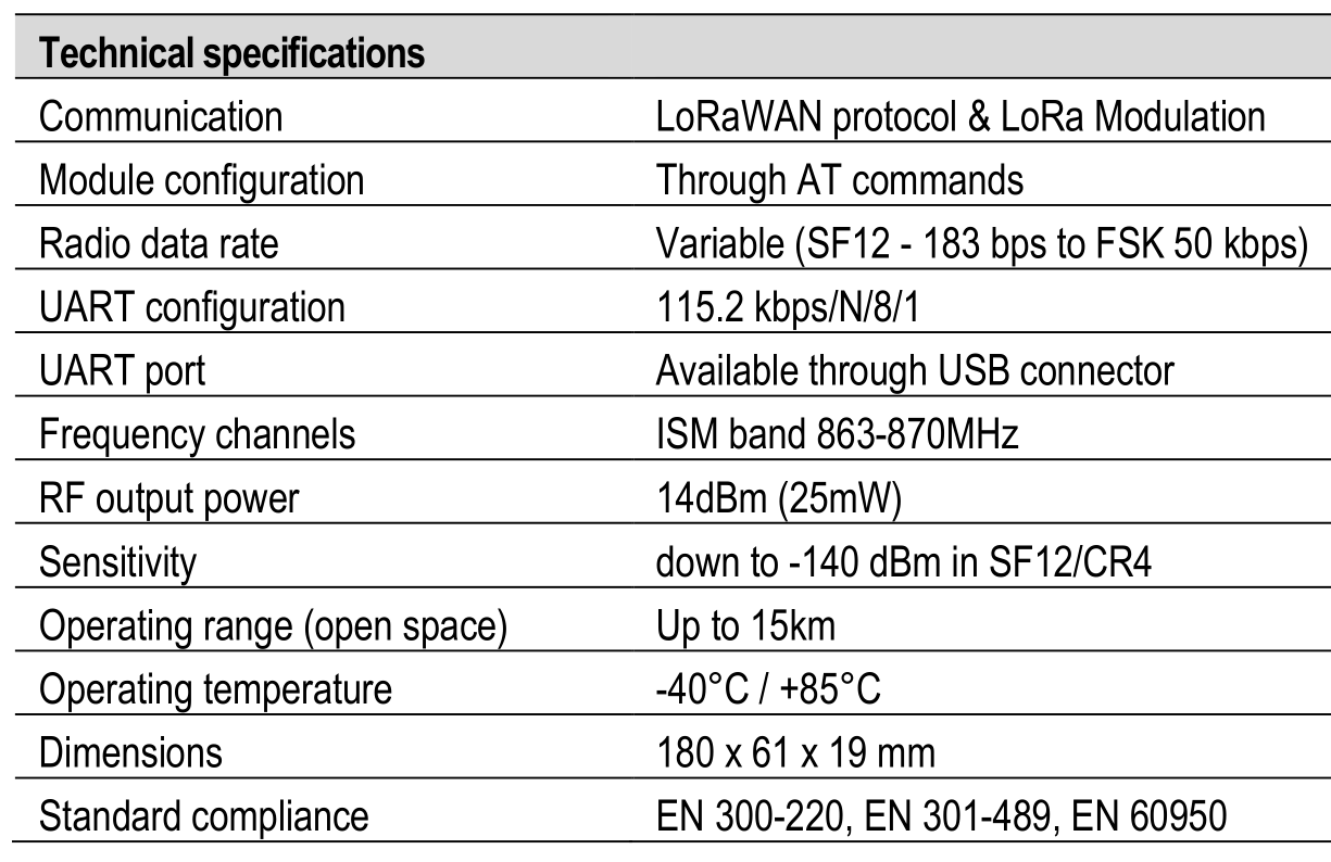
Equipment list
Before you are able to configure the Adeunis RF LoraWAN Demonstrator you need the following equipment:
- Adeunis RF LoraWAN Demonstrator:
- USB cable
- Terminal emulator to send the commands to the test device
- LoRa gateway in the range of the Adeunis RF LoraWAN Demonstrator
- Network server (Actility TPW)
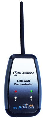
Network Diagram
Connection to the Adeunis RF LoraWAN Demonstrator
- Connect the module to a PC. The device will create a new serial device (COMx on Windows and /dev/ttyACMx on Linux)
- Open a terminal session to the serial device/port with the following parameters: bitrate: 115200, 8 bits, no parity, 1 stop bit, no flow control.
Commands need to be terminated with <CR><LF> and the device does not echo back send commands by default.
After connecting to the device, and turning it on, you should instantly receive information regarding the test packets sent out.
For example:[jensd@testdev ~]$ python -m serial.tools.miniterm -e -p /dev/ttyACM1 -b 115200 --- Miniterm on /dev/ttyACM1: 115200,8,N,1 --- --- Quit: Ctrl+] | Menu: Ctrl+T | Help: Ctrl+T followed by Ctrl+H --- *** CYCLE START *** AdrAckCount:-64 FCtrl:ADR FCnt:0 TxPay=40640A0004800000018E190100FFFF TxMicPay=47A187ED StartTx/C0/F=868100000/SF12/BW125 StartRx1/C0/F=868100000/SF12/BW125 ReceiveRx1/0 StartRx2/F=869525000/SF12/BW125 ReceiveRx2/0 *** CYCLE END *** *** CYCLE START *** ...
- After you have ensured that you can communicate with the device, you can start the configuration by entering the configuration mode. This can be done by entering the following key sequence: \F\F\F\F+++ The device will respond with CM to confirm that you have entered Configuration Mode:
\F\F\F\F+++CM
- After configuring the device as explained below, you can leave configuration mode by sending ATO. This will restart the test cycle and sending LoRa packets:
ATO
O

*** CYCLE START ***
...
Configure the device for ABP
- Enter Configuration Mode:
\F\F\F\F+++CM
ATT63 PROVIDER
O
- To set the NwkSKey you need to set 4 variables in a row. The O is the response of the device to confirm it has accepted the value set:
For example, to set a NwkSKey to 12345678123456781234567812345678:ATS222=12345678 O ATS223=12345678 O ATS224=12345678 O ATS225=12345678 O
- To set the AppSKey you need to set 4 variables in a row. The O is the response of the device to confirm it has accepted the value set:
For example, to set a AppSKey to 12345678123456781234567812345678:ATS216=12345678 O ATS217=12345678 O ATS218=12345678 O ATS219=12345678 O
- Set the DevAddr:
ATS281=04000A64
O
- Set the device to use ABP (0=ABP, 1=OTAA)
ATS221=0
O
- Save the settings in the device:
AT&W
O
- Leave configuration mode:
ATO
O
Configure the device for OTAA
- Enter Configuration Mode:
\F\F\F\F+++CM
ATT63 PROVIDER
O
- To set the AppKey, you need to set 4 variables in a row. The O is the response of the device to confirm it has accepted the value set.
For example to set the AppKey to 12345678123456781234567812345678ATS216=12345678 O ATS217=12345678 O ATS218=12345678 O ATS219=12345678 O
- To set the AppEUI, you need to set 2 variables in a row. The O is the response of the device to confirm it has accepted the value set.
For example to set the AppEUI to: FEDCBA9876543210ATS214=FEDCBA98 O ATS215=76543210 O
- Set the device to use OTAA (0=ABP, 1=OTAA)
ATS221=1
O
- Save the settings in the device:
AT&W
O
- Leave configuration mode:
ATO
O
Add the device to the Actility TPW Device Manager for ABP
- Log in to the TPW Device Manager
- In the “Add Devices” section, click “Create”:
- Fill in the required information as configured the device above for ABP:
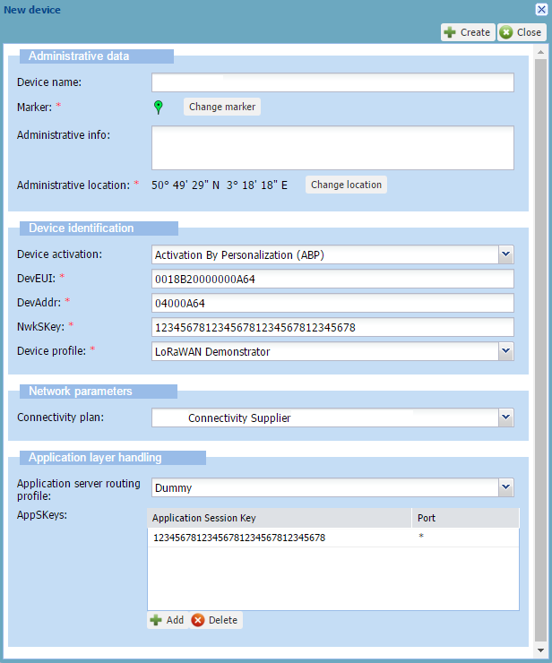
- Click “Create”
Add the device to the Actility TPW Device Manager for OTAA
- Log in to the TPW Device Manager
- In the “Add Devices” section, click “Create”:
- Fill in the required information as configured the device above for OTAA:
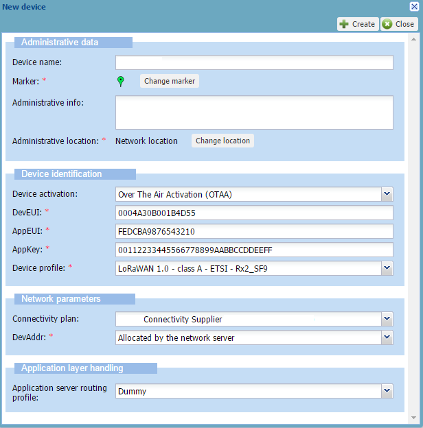
- Click “Create”
Send Data
The device is immediately joining the network and start to send data, depending on what was configured as explained above.
You can track what the device is sending and receiving from the serial connection.
For example:
*** CYCLE START *** AdrAckCount:-35 FCtrl:ADR FCnt:29 TxPay=40640A0004801D00018E1E1E000CDB TxMicPay=95E51390 StartTx/C2/F=868500000/SF12/BW125 StartRx1/C2/F=868500000/SF12/BW125 ReceiveRx1/0 StartRx2/F=869525000/SF12/BW125 ReceiveRx2/0 *** CYCLE END *** *** CYCLE START *** AdrAckCount:-62 FCtrl:ADR FCnt:44 TxPay=40640A0004802C0001AE1E2D010CDB TxMicPay=BA48BFC4 StartTx/C0/F=868100000/SF12/BW125 StartRx1/C0/F=868100000/SF12/BW125 ReceiveRx1/30/ValidRx FCtrl: FCnt:3 RxLoRaPay=60640A000400030000C0B1D5E498D7480F09A3BDF85DB833FA811C7A9B46 !ReplayConf RxMacPay=03111F00010705B85E8450070688668450 ProcessFportMac RxMAC=3/LinkADRReq/SF11/P=14dBm/R=1/C=C0-C1-C2-C3-
C4 RxMAC=7/NewChannelReq/F=867500001/SF12/SF11/SF10/S F9/SF8/SF7/E RxMAC=7/NewChannelReq/F=867700001/SF12/SF11/SF10/S F9/SF8/SF7/E *** CYCLE END *** NACK/C0/868100000Hz/-98dBm/-2dB
Troubleshoot
Check if the base station receives the LoRa data over radio from the RN2483.
This information should be available in the TRACE.log from the Actility LRR running on a base station which is in the range of the RN2483.
Example of received uplink and downlink data:
12:58:57.160 (6449) [../lgw_x8.c:879] PKT RECV tms=013043482 tus=155780756 status=CRCOK sz=19 freq=867300000 delay=149 mod=0x01 bdw=BW125 spf=SF12 ecc=CC4/5 channel=5 nam='LC5' G2
12:58:57.160 (6449) [../lgw_x8.c:897] rf0: valid=1 finetime=0 timestamp=000000000 chip=0 chan=1 snr=2.000000 rssi_chan=-89.000000 rssi_sig=0.000000 rssi_sig_std=0
12:58:57.160 (6449) [../lgw_x8.c:897] rf1: valid=1 finetime=0 timestamp=000000000 chip=1 chan=1 snr=3.750000 rssi_chan=-84.000000 rssi_sig=0.000000 rssi_sig_std=0
12:58:57.160 (6449) [../lgw_x8.c:946] PKT RECV data='40640a0004802b00016fcad867283060f1abfb' seq=43 devaddr=04000a64
12:58:57.160 (7795) [../main.c:2666] packet sent to LRC=0 lrrid=68ba4776 by order rssi=-84.000000 snr=3.750000

12:58:57.419 (7795) [../main.c:1887] MACLORA SEND seq=2 ack=0 devaddr=04000a64 w=0 major=0 minor=3 len=30 tmoa=1482.752000ms flg='RDY' deveui=0018b20000000a64/2
12:58:57.419 (7795) [../main.c:1930] MAC SEND trip=474 avtrip=0 dvtrip=0 mxtrip=0 long delay postpone=451 in MainQ
12:58:57.870 (7795) [../lgw_gen.c:946] LGW DELAY postponed=474/925 rqtdelay=1000 delay=75 busydur=0
12:58:57.925 (6449) [../lgw_x8.c:1164] PKT SEND tms=013044312/979 status=3 sz=30 left=0 freq=867300000 mod=0x01 bdw=BW125 spf=SF12 ecc=CC4/5 pr=8 nocrc=1 ivp=1 pw=17
12:58:57.925 (6449) [../lgw_x8.c:1187] LGW DELAY tmao request=1631ms + sched=75ms
12:58:57.925 (6449) [../lgw_x8.c:1230] PKT SEND async dur=1482.751953ms diff=980ms data='60640a0004000200009666150cc2110f75fa4bf8a4279df3b0be05874130' seq=2 devaddr=04000a64
12:58:57.925 (7795) [../main.c:1658] PKT SEND INDIC deveui=0018b20000000a64 fcnt=2 deliv=1 c1=0 c2=0 rtt=474
12:58:57.925 (7795) [../main.c:2662] indic sent to LRC=0 lrrid=68ba4776 by order
Once you see that the gateway received the packet and forwarded it to the LRC, we can further troubleshoot using the Wireless logger:
Incoming data seen in the wLogger: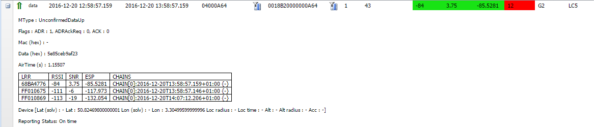
MAC data sent back by the LRC to the device in wLogger:
From the Device Manager, you should also see more information:
Decoding the payload
The data sent by the LoRaWAN Demonstrator and returned to your application server by Actility TPW is not really in a human readable format.
An example of the JSON data sent after the LoRaWAN Demonstrator sent a message to Actility TPW:
{"DevEUI_uplink": {"Time": "2017-10-05T14:48:21.944+02:00","DevEUI": "0018B20000000A64","FPort": "1","FCntUp": "2","ADRbit": "1","MType": "2","FCntDn": "3","payload_hex": "ae1a03010cd8","mic_hex": "9c00ea40","Lrcid": "00000201","LrrRSSI": "-93.000000","LrrSNR": "6.750000","SpFact": "12","SubBand": "G1","Channel": "LC3","DevLrrCnt": "2","Lrrid": "68BA4776","Late": "0","LrrLAT": "50.824699","LrrLON": "3.304996","Lrrs": {"Lrr": [{"Lrrid": "68BA4776","Chain": "0","LrrRSSI": "-93.000000","LrrSNR": "6.750000","LrrESP": "-93.832695"},{"Lrrid": "080E0F48","Chain": "0","LrrRSSI": "-99.000000","LrrSNR": "2.500000","LrrESP": "-100.937759"}]},"CustomerID": "100000778","CustomerData": {"alr":{"pro":"LORA/Generic","ver":"1"}},"ModelCfg": "0","DevAddr": "04000A64"}}
To extract the real information from the above JSON, and more importantly, to extract the values from the payload, you can use the following Python snippet:
import json

#extract details regarding LoRa device
lora_deveui=json_data['DevEUI_uplink']['DevEUI']
lora_payload=json_data['DevEUI_uplink']['payload_hex']
lora_fport=json_data['DevEUI_uplink']['FPort']
lora_devaddr=json_data['DevEUI_uplink']['DevAddr']

#find flags in first byte
#temperature
tmp_present=int(lora_payload[0:2],16)&128
#acceleration detected
acl_detect=int(lora_payload[0:2],16)&64
#button pressed
btn_pressed=int(lora_payload[0:2],16)&32
#GPS info
gps_present=int(lora_payload[0:2],16)&16
#F up count
fup_present=int(lora_payload[0:2],16)&8
#F down count
fdw_present=int(lora_payload[0:2],16)&4
#battery (mV)
bat_present=int(lora_payload[0:2],16)&2
#SNR/RSSI
sig_present=int(lora_payload[0:2],16)&1

#offset becomes 8 when GPS data is present
offset=0
event="interval"

if bool(tmp_present):
	temperature=int(lora_payload[2:4],16)
	print "temperature: %s",temperature

if bool(acl_detect):
	event="motion"

if bool(btn_pressed):
	event="button"

if bool(gps_present):
	print "GPS location sent"
	offset=8

if bool(fup_present):
	print "up count:"+str(int(lora_payload[4+offset:6+offset],16))

	if bool(fdw_present):
	print "down count:"+str(int(lora_payload[6+offset:8+offset],16))

if bool(bat_present):
	battery=str(int(lora_payload[8+offset:10+offset],16))+str(int(lora_payload[10+offset:12+offset],16))
	print "battery: %s mV",battery

if bool(sig_present):
	print "RSSI:"+str(int(lora_payload[12+offset:14+offset],16))
	print "SNR:"+str(int(lora_payload[14+offset:16+offset],16))

print "event type: %",event
As you can see in the above code snippet, the first byte in the hex payload contains a flag that indicates the contents of the rest of the payload (lines 9-25).
The next part of the code, starting from line 31, is extracting the rest of the data from the hex payload and converts it to human readable values.
Documentation
For more information and background on the Adeunis RF LoraWAN Demonstrator:
Hi Jens,
How / where can I obtain the Dev EUI address form the Adeunis RF tester device? in case I choose for the OTAA config.
Regards,
Arnold
Hi Arnold,
The DevEUI is hardcoded in the device and is chosen/provided by the manufacturer (Adeunis). Normally, at least with the two test device I got, there should be a sticker on the back of the device that shows the S/N. This is equal to the DevEUI.
Hi Jens,
Thanks for your instruction. But, I still have one problem, after I added the device to the Actility TPW Device Manager for ABP, I still cannot the sending data. I checked the steps and it should be ok. Could you give me some suggestions?
Hi,
i have the same setup as you do, but i have a wierd problem, if the GW is near the Device it joins fine.
if the GW is far away it never joins, even though i see the join accept on the TPW. and i have a good RSSI and SNR.
is there a way to see if the packet reached the device?
thanks.
Hello jens
I was reading the manual and i saw that you can scheduled confirmed and unconfirmed uplinks.
I tried it, however i cannot configure a timing to send those uplinks and it send it really fast (one oplink every 3 seconds or less). Is there a way to modify it?