
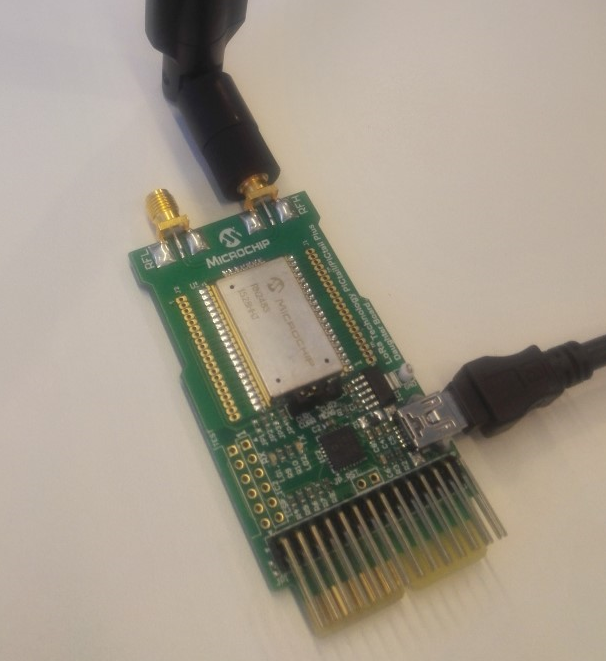
The Microchip RN2483 is a LoRa class A module widely available. In a normal, end-user scenario, LoRa endpoints (or devices/sensors) come with preconfigured parameters but before the module can be used, it needs to be configured with those parameters to use it in the LoRa network. What parameters to configure depends on the type of activation. For this post, I’ve been using the RN2483 based PICtail test-board.
When using a LoRa test-device, the parameters need to be set manually before the device can send data. How to set these parameters completely depends on the type of chip that is used in the device. Most of the times this information can be found in the documentation but I found it often difficult to translate the raw info to hands-on usable information so I decided to figure everything out and write a post about it.
After configuring the necessary parameters in the device, they need to match with the device added to the network server in your LoRa network before it will accept data sent by this device. For this post, I will use Actility TPW (ThingPark Wireless) Device Manager
About the Microchip RN2483
The RN2483 is a fully-certified 433/868 MHz module based on wireless LoRa technology. The RN2483 utilizes a unique spread spectrum modulation within the Sub-GHz band to enable long range, low power, and high network capacity. Configuration is done with ASCII command interface over UART. The test board RN2483 PICTail contains a usb port with integrated USB to serial.
Equipment list
Before you are able to configure the RN2483 you need the following:
- RN2483 PICTail
- USB cable
- Terminal emulator to send the commands to the test device
- LoRa gateway in the range of the RN2483 device
- Network server (Actility TPW)
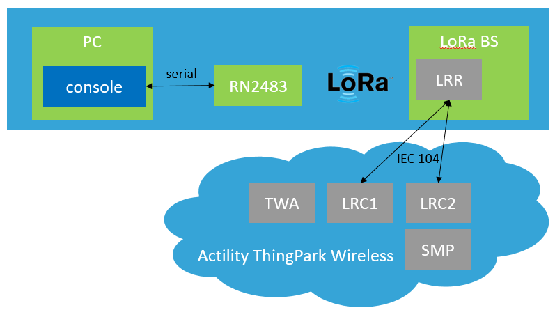
Network diagram
Connection to the RN2483
- Connect the module to a PC. The device will create a new serial device (COMx on Windows and /dev/ttyACMx on Linux)
- Open a terminal session to the serial device/port with the following parameters: bitrate: 57600, 8 bits, no parity, 1 stop bit, no flow control.
Commands need to be terminated with <CR><LF> and the device does not echo back send commands by default.
After connecting to the device, you can test the communication by sending “sys get ver” which should return the current FW version of the board.
For example:[jedepuyd@testdev ~]$ python -m serial.tools.miniterm -e -p /dev/ttyACM0 -b 57600 --- Miniterm on /dev/ttyACM0: 57600,8,N,1 --- --- Quit: Ctrl+] | Menu: Ctrl+T | Help: Ctrl+T followed by Ctrl+H --- sys get ver RN2483 1.0.1 Dec 15 2015 09:36:30
- After you have ensured that you can communicate with the device, you can start the configuration.
Configure the device for ABP
- Get the hwEUI (physical address) of the module
sys get hweui
0004A30B001B4D55
- Set the NwkSKey:
mac set nwkskey 12345678123456781234567812345678
ok
- Set the AppSKey
mac set appskey 12345678123456781234567812345678
ok
- Set the DevAddr:
mac set devaddr 001B4D55
ok
- (optionally) Turn on ADR (Adaptive Data Rate):
mac set adr on
ok
- (optionally) Set the transmit power:
radio set pwr 14
ok
- Save the settings in the device:
mac save
ok
Configure the device for OTAA
- Get the hwEUI (physical address) of the module
sys get hweui
0004A30B001B4D55
- Set the AppKey:
mac set appkey 00112233445566778899AABBCCDDEEFF
ok
- Set the AppEUI:
mac set appeui FEDCBA9876543210
ok
- Save the settings in the device:
mac save
ok
Add the device to the network server (Actility TPW Device Manager) for ABP
- Log in to the TPW Device Manager
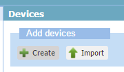
- In the “Add Devices” section, click “Create”:
- Fill in the required information as configured the device above for ABP:
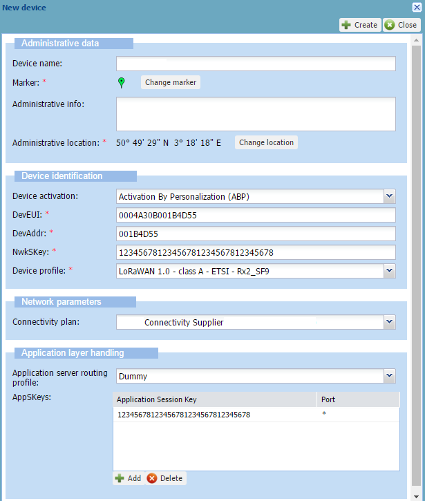
- Click “Create”
Add the device to the Actility TPW Device Manager for OTAA
- Log in to the TPW Device Manager
- In the “Add Devices” section, click “Create”:
- Fill in the required information as configured the device above for OTAA:
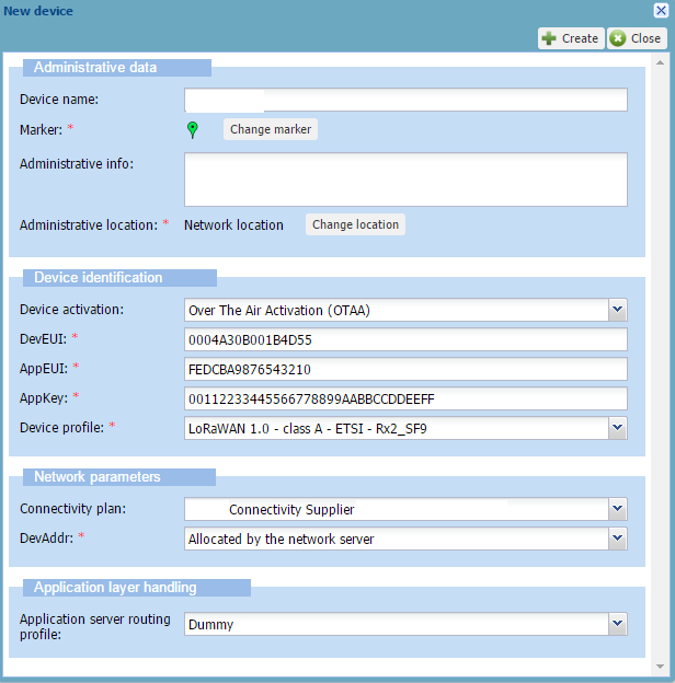
- Click “Create”
Join with ABP
Although there is no real join process when using ABP, you need to tell the device that it is using ABP and not OTAA:
mac join abp
ok
accepted
Join with OTAA
For OTAA, there is a real join process and you require the network server to acknowledge your join before you will be able to send data:
mac join otaa
ok
accepted
Send data
There are two ways to send data with LoRa: confirmed (which will be confirmed by a downlink frame: like TCP) and unconfirmed (no confirmation: like UDP).
The format of sending data for RN2483 is as follows:
mac tx <type> <FPort> <payload>
For example:
mac tx uncnf 1 DEAD
ok
mac tx cnf 1 BEEF
ok
mac_tx_ok
mac_rx 1
Troubleshoot
Check if the base station receives the LoRa data over radio from the RN2483.
This information should be available in the TRACE.log from the Actility LRR running on a base station which is in the range of the RN2483.
Example of received uplink and downlink data:
09:21:53.020  (6449) [../lgw_x8.c:879] PKT RECV tms=000019464 tus=016606332 status=CRCOK sz=15 freq=868300000 delay=93 mod=0x01 bdw=BW125 spf=SF12 ecc=CC4/5 channel=2 nam='LC2' G1
09:21:53.020  (6449) [../lgw_x8.c:897]     rf0: valid=1 finetime=0 timestamp=000000000 chip=0 chan=6 snr=0.250000 rssi_chan=-91.000000 rssi_sig=0.000000 rssi_sig_std=0
09:21:53.020  (6449) [../lgw_x8.c:897]     rf1: valid=1 finetime=0 timestamp=000000000 chip=1 chan=6 snr=-1.250000 rssi_chan=-87.000000 rssi_sig=0.000000 rssi_sig_std=0
09:21:53.020  (6449) [../lgw_x8.c:946] PKT RECV data='80554d1b008007000187134d9c22b8' seq=7 devaddr=001b4d55
09:21:53.020  (7795) [../main.c:2666] packet sent to LRC=0 lrrid=68ba4776 by order rssi=-87.000000 snr=-1.250000

09:21:53.262  (7795) [../main.c:1887] MACLORA SEND seq=6 ack=0 devaddr=001b4d55 w=0 major=0 minor=3 len=30 tmoa=1482.752000ms flg='RDY' deveui=0004a30b001b4d55/6
09:21:53.262  (7795) [../main.c:1930] MAC SEND trip=402 avtrip=0 dvtrip=0 mxtrip=0 long delay postpone=523 in MainQ
09:21:53.624  (6449) [../lgw_x8.c:879] PKT RECV tms=000020068 tus=017217827 status=CRCERR sz=73 freq=867500000 delay=0 mod=0x01 bdw=BW125 spf=SF7 ecc=CC4/6 channel=6 nam='LC6' G2
09:21:53.624  (6449) [../lgw_x8.c:897]     rf0: valid=0 finetime=0 timestamp=000000000 chip=0 chan=0 snr=0.000000 rssi_chan=0.000000 rssi_sig=0.000000 rssi_sig_std=0
09:21:53.624  (6449) [../lgw_x8.c:897]     rf1: valid=1 finetime=0 timestamp=000000000 chip=1 chan=2 snr=-11.500000 rssi_chan=-93.000000 rssi_sig=0.000000 rssi_sig_std=0
09:21:53.785  (7795) [../lgw_gen.c:946] LGW DELAY postponed=402/925 rqtdelay=1000 delay=75 busydur=0
09:21:53.861  (6449) [../lgw_x8.c:1164] PKT SEND tms=000020370/999 status=3 sz=30 left=0 freq=868300000 mod=0x01 bdw=BW125 spf=SF12 ecc=CC4/5 pr=8 nocrc=1 ivp=1 pw=16
09:21:53.861  (6449) [../lgw_x8.c:1187] LGW DELAY tmao request=1631ms + sched=75ms
09:21:53.861  (6449) [../lgw_x8.c:1230] PKT SEND async dur=1482.751953ms diff=1001ms data='60554d1b0020060000ad4151a85e3b0807b63aeb03f93a85261bc4d2ce1c' seq=6 devaddr=001b4d55
09:21:53.861  (7795) [../main.c:1658] PKT SEND INDIC deveui=0004a30b001b4d55 fcnt=6 deliv=1 c1=0 c2=0 rtt=402
09:21:53.862  (7795) [../main.c:2662] indic sent to LRC=0 lrrid=68ba4776 by order
Once you see that the gateway received the packet and forwarded it to the LRC, we can further troubleshoot using the Wireless logger:
Data seen in the wLogger for the unconfirmed uplink data:
Data seen in the wLogger for the confirmed uplink data: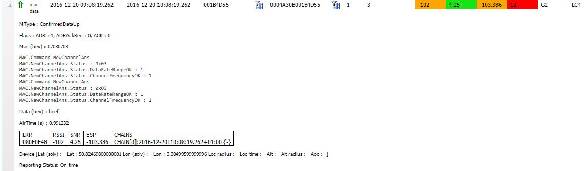
Data seen for the confirmation downlink frame: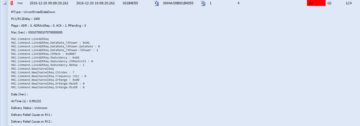
Documentation
For more information and background on the RN2483:
Hello!
I connect my RN2483 to my computer but it doesn’t matter which terminal program I use (PuTTy, Hyperterminal, minicom for linux) I have no possibility to write any command…. I just get a black screen when I can’t type. Do you know how I can fix this?
Thank you,
Mirian
The best is TeraTerm with configuration Setup -> Terminal -> Transmit: CR+LF
Hi! In my case I can the but I don’t get any response!! when I reset the device it shows the the version but when I type I don’t receive anything. What can I do?
What do you mean with commands need to be terminated with ? how can I do that?
terminated mens after command u have to attch \r\n
if you used teraterm on CR+LF
example “sys reset\r\n”
Hi Mirian,
By default, most terminal programs do not have echo feedback enabled, which means they count on the device you communicate with to echo back the characters which you typed. In the case of the RN2483 this doesn’t happen so you need to enable this in your terminal client. (option -e for miniterm)
Every serial device has requirements on how you terminate (and confirm) an entered command. for the RN2483, in the datasheet it’s defined that, after entering a command, you can execute it by sending (Carriage Return + Line Feed). How to configure that depends again on your terminal client.
I want to transmit data from one RN2483 module and receive to another RN2483 module using MAC protocol and not by using radio point to point transmission commands. Please help. Thankyou
how to recieve the data from rn-2483 module to lora gateway(down link process)